Abstract
The Kelvin Probe Method for measuring the difference in work function between two surfaces, known as the "Contact Potential Difference" (CPD), is a well-known technique in surface science. It permits accurate and precise measurements of CPDs in a wide range of technologically important environments, including air, (non-conducting) liquids, and vacuum.
Unfortunately, the traditional implementation of the method, using a lock-in amplifier, suffers from two significant sources of systematic error: the spacing dependence of the feedback gain involved in a lock-in technique [1], and the spacing dependence introduced by stray capacitances, or "micro phonics" [2]. Any Kelvin Probe measurements which do not account for and eliminate these effects, may contain essentially unpredictable systematic errors of several hundreds of millivolts.
We describe an implementation of the Kelvin Probe technique which relies on off-null measurements and which permits essentially spacing-independent measurements to be made.
The Kelvin Probe Technique
Figure 1 shows a schematic diagram of the Kelvin Probe apparatus. A probe is held above the surface of interest and oscillated mechanically. When dissimilar materials are used, a contact potential difference (CPD) due to the difference in work functions exists between the probe and sample, and an ac current will flow through the circuit. If an external potential VB is applied to the probe that exactly cancels out the CPD, the current will be zero. VB is then exactly equal to the CPD.
Traditionally, a lock-in amplifier is used to measure the signal and negative feedback used to null out the signal. Then, simply by measuring the feedback voltage and dividing by the gain of the preamplifier, the CPD could be determined. There are several problems associated with this technique.
- This method suffers from a poor signal to noise ratio due to having to work at the null point where, by definition, the signal to noise ratio is zero.
- Two sources of systematic error related to the mean spacing between the plates exist.
The first characteristic of the lock-in technique is that the capacitance of the probe/sample interface can significantly affect the gain of the feedback loop.[1] Reducing this dependence requires using higher preamplifier gains, causing greater instability in the feedback loop. Another dependence on mean spacing results from unintended vibrations in the head. These vibrations induce their own currents resulting in a false signal. These "stray capacitances" can lead to errors in the measured CPD of the order of tens or hundreds of millivolts[2].
The Off-Null Variation
We have implemented a variation on the traditional Kelvin Probe method based on an "off-null" technique [2]. The amplitude of the current measured by the preamplifier is proportional to the potential difference across the plates. By measuring the signal amplitude as a function of applied backing potential and interpolating to the point of zero current, the backing potential required to null out the signal is found. This, as before, is simply the CPD.
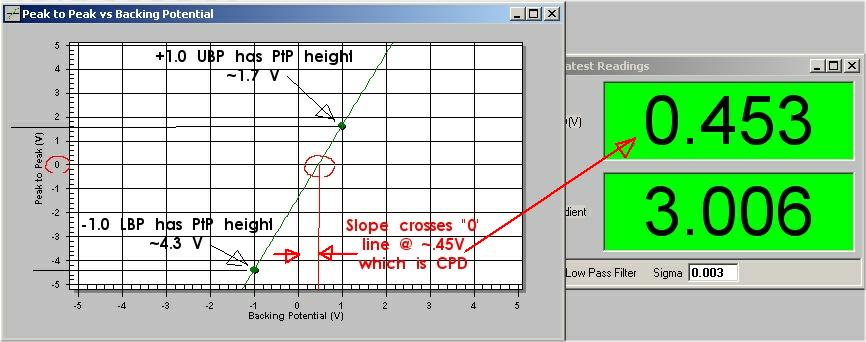
The off-null method has the advantage that no feedback is used, and thus the gain of the preamplifier is independent of the mean spacing of the probe and sample. In addition, for off-null conditions, the signal to noise ratio is very good and, therefore, interpolation can be performed very accurately.
Even this method suffers, however, from systematic errors due to stray capacitances. In Figure 2, the line labeled Unoptimized Probe shows the CPD between a stationary copper substrate and an oscillating stainless steel probe, measured as a function of the mean spacing. The probe and sample were clean, but were covered by an uncharacterized oxide layer. As can be seen from the data, the measured CPD varies by almost one hundred millivolts over a range of spacings of approximately 250 microns. Clearly, for any accurate measurement, this uncertainty is unacceptable.
Minimizing the Effect of Stray Capacitances.
The first step in minimizing stray capacitances is to reduce the stray vibrations themselves. All loose wires should be rigidly held in place, with care being taken not to add unnecessary capacitance to the circuit (for instance, gluing wires to a surface can add a huge capacitance, making the RC time constant so large that the system is essentially unusable). In addition, the wire that connects the moving parts to the rigid head, should be made short, with minimal excess length. It should also be very thin, and kept far from any stationary objects to reduce the capacitance to those objects. By making it short, the number of resonant modes and frequencies is reduced; by making it thin, the resonant frequencies can be raised above the range in which the probe will operate.Even in a well-designed head, vibrations will exist and introduce stray capacitances. Therefore, we have developed a technique which can reduce the effect of the vibrations even further. First, the false signal due to stray capacitance is measured by withdrawing the sample far from the probe so that the true KP signal is negligible. With stray capacitances present, there will still be a "signal". The amplitude of this signal is measured as a function of frequency over the range of frequencies available - in this case from 50 to 500 Hz. The minima in this spectrum show the frequencies at which the stray capacitances contribute the least. By taking data at these non-resonant frequencies, the effects of stray capacitance on the measured CPD can be reduced even further.
Figure 3 shows a graph of the stray signal amplitude for two different heads, as a function of the probe oscillation frequency, at constant probe driving voltage. For a constant driving voltage, the amplitude of oscillation of the probe will vary with frequency. In particular, at the resonant frequency, the amplitude will be large.
The line labeled Unoptimized Probe shows the signal for a head containing several loose wires, capable of vibrating relative to a grounded metal object. The line labeled Optimized Probe shows the stray capacitance signal for the same head after optimization. Two important features are apparent.
- For the first probe, the average signal level is significantly higher than the second.
- Secondly, the optimized head still shows a large peak in amplitude near the resonance of the probe. We believe this is due to the very large (>2mm) amplitude of vibration of the probe at this frequency.
The effect of the stray capacitance signal is to introduce an error into the measured CPD:
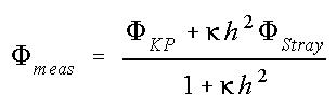
where h is the mean spacing between probe and sample and κ is a constant dependent on the amplitudes of oscillation, the relative "square areas" of the probe and vibrating wire, and the mean spacing of the vibrating wire from the nearby surface. This curve is also displayed in Figure 3. In this fit there are two free fit variables, κ and Φ Stray. For the line shown in Figure 3, κ = 0.005 and Φ Stray= -0.615).
Conclusions:
The dependence of the measured contact potential difference (CPD) on the mean spacing between the probe and sample represents a major source of systematic error in the Kelvin Probe technique. This error is essentially unpredictable and may be as large as hundreds of millivolts. As a result, any measurements made which do not explicitly account for these errors may contain errors of this magnitude.There are two main sources of this dependence: the dependence of the feedback amplifier gain on the capacitance of the probe/sample gap for lock-in techniques; and the effects of stray capacitances (micro phonics) on the measured CPD.
We show how the use of an "off-null" technique eliminates the former, while careful head design and selection of probe oscillation frequency can eliminate the latter. As a result, we obtain CPD measurements that are independent to within a few millivolts, of the mean spacing over a typical experimental range of 250 microns.
References
1. Rossi, F. Contact potential measurement: Spacing dependence errors. Rev Sci Instrum 63 (9), 4174-4181 (1992).2. Baikie, I. D. et al, Analysis of stray capacitance in the Kelvin method. Rev Sci Instrum 62 (3), 725-735 (1991)